
Introduction
- X-rays are short wave electromagnetic radiation, part of the electromagnetic spectrum.
- X-rays have higher frequencies and energies than visible light, microwaves and radiowaves.
- Diagnostic x-rays typically have energies between 20 and 150 keV. A few imaging modalites using x-rays including conventional radiography and computed tomography.
- X-ray is an ionizing radiation. This term is given to radiation that are energetic enough to displace orbiting electrons from the atoms in the absorbing medium, thus forming positive ions.
- Ionizing radiation damages the cell by indirectly or directly damage the DNA molecules (further discussion on this topic is in another lecture).

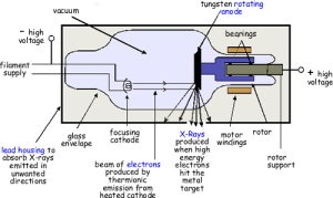
Production of X-rays:
- X-rays are produced when high speed electrons decelerate rapidly. This is achieved by passing a very high voltage across two terminals placed in an evacuated tube. One of the terminals, the cathode, is a tungsten alloy filament. The other terminal, the anode is a tungsten alloy target set in a disc of copper. The cathode is heated and it liberates free electrons. When a high voltage is applied across the two terminals, the electrons are attracted towards the anode at high speed. They hit the tungsten target and x-rays are produced.
- Most of the electrical energy (99%) entering the tube is converted to heat and the tube heating is often the limiting factor in how much the x-ray tube can be used. About 1% of the electrical energy entering the tube is converted into x-rays. Of these, only a small portion of useful x-rays escapes through an opening in the metal casing surrounding the tube, the remainder are absorbed by the casing.
Interactions of x-rays with matter
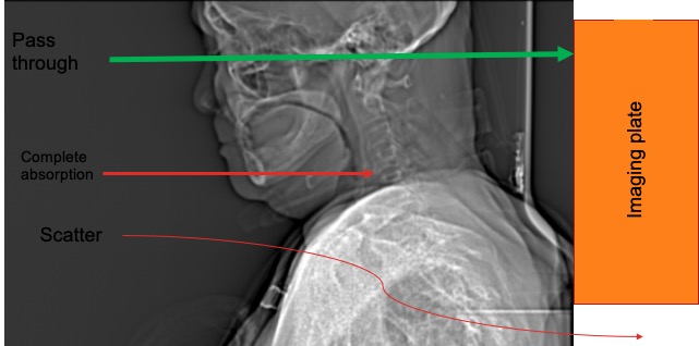
- There are a few ways how x-rays interact with matter.
- Pass through: X-rays may pass completely through tissues and hit the image recording device. This is the type of x-rays that we want in medical use.
- Complete absorption: x-ray energy is completely absorbed by the tissue and no imaging information results. This is unwanted type of x-rays.
- Partial absorption with scatter: where the scattering involves a partial energy absorption in the tissue with the resulting scattered x-rays having less energy and a different trajectory. Scatter radiations tend to degrade the image quality and is the primary source of radiation to operator and staff.
Absorption of x-rays
- Radiographic images depend on the amount of x-rays absorbed as they pass through the body.
- The visibility of structures and diseases depends on this differential absorption.
- This different absorption depends on the density and atomic number of the various tissues through which it passes.
- X-rays turn x-ray film black. The less dense a material, the more x-rays get through and the blacker the film.
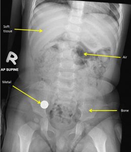
- Five basic radiographic densities are recognised on plain radiographs
- gas/air such as seen of lung, bowel and stomach
- fat-dark grey such as subcutaneous layer, retroperitoneal fat
- soft tissues/water-light grey such as solid organ, muscles and fluid-filled structures such as bladder
- bone – off-white
- Contrast material/metal-bright white
- Bones and other calcified structures absorbs the most and so the these structures appear virtually white. The soft tissues such as muscle, blood and viscera appear the same shade of grey on conventional radiography. Fat absorbs slightly fewer x-rays and therefore appears a little blacker than the other soft tissues.
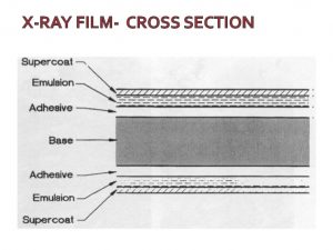
Photographic effect and image production
- X-rays cause blackening of the emulsion of a developed photographic film.
- In practice, the effect of the x-ray beam are usually intensified by the use of fluorescent screens which emits light when exposed to x-rays.
- The photographic effect is sandwiched between two fluorescent screens in a special light tight cassette. When exposed to x-rays it is mainly the light emitted from the fluorescent screens that causes blackening of the developed film.
- Computed radiography differs from conventional radiography as it used phosphor plate to capture x-ray exposure information.
- The electrons trapped in phosphur plate is then ‘read’ by a device that uses lasers to compel the electrons to emit light.
- This pattern is then electronically stored as digital image.
- The ability of the observer to manipulate the brightness and contrast of the digital imaging is a great advantage of this technique.
Projection in conventional radiography
- Projections are usually described the path of the x-ray beam.
- Thus, a posteroanterior (PA) view is where the beam passes form the back to the front.
- In AP view, the image is taken from the front.
- The term ‘frontal’ refers to either PA or AP projection.
Magnification in radiography
- All conventional x-ray images show some magnification, because the x-ray tube sends out a diverging beam of x-rays.
- The closer the object is to the film, the less the magnification.
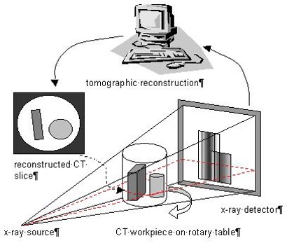
Computed tomography (CT scan)
- CT scan is an imaging technique whereby cross-sectional images are obtained with the use of x-rays.
- Computed tomography differs from conventional radiography in that it uses a more sensitive x-ray detection system than photographic film. It uses gas or crystal detectors and then manipulates the data from the detectors using a computer.
- The x-rays are generated in similar fashion. The x-ray tube rotates around the patient. In some systems, the detector also moves but in others they are arranged in a stationary ring around the patient.
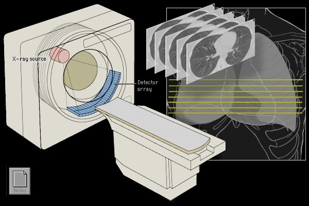
The patient lies with the part to be examined within the gantry housing the x-ray tube and detectors. The section level and thickness to be imaged are selected by radiographers. By moving the patient through the gantry, multiple sections can be imaged allowing a picture of a body to be built up. Thinner sections provide more accurate information. The data obtained from each set of exposures are reconstructed into an image by computer manipulation. The computer calculates the attenuation absorption value of each picture element (pixel). Since each pixel has a definite volume, the attenuation value recorded represents the mean value of that volume of tissue (voxel). The resulting images are displayed on a television monitor.
The attenuation values are expressed on an arbitrary scale Hounsfield units with water density being 0, air density being minus 1000 units and bone density being plus 1000 units. The range and level of densities visualized on a particular image is known as the window width and the mean level as window level or window centre.
Computed tomography is usually performed in the axial plane. However, it is possible to reconstruct images in other planes such as coronal or sagittal plane.
Numerous artefacts can occur on CT images. The two most common are produced by movement and those objects with high density causing radiating linear streak artifacts. It causes degradation of the surrounding structures.
Mammography
Mammography uses lower kV for higher image contrast and higher mAs for shorter exposure times compared with the other radiographic examinations.
Fluoroscopy
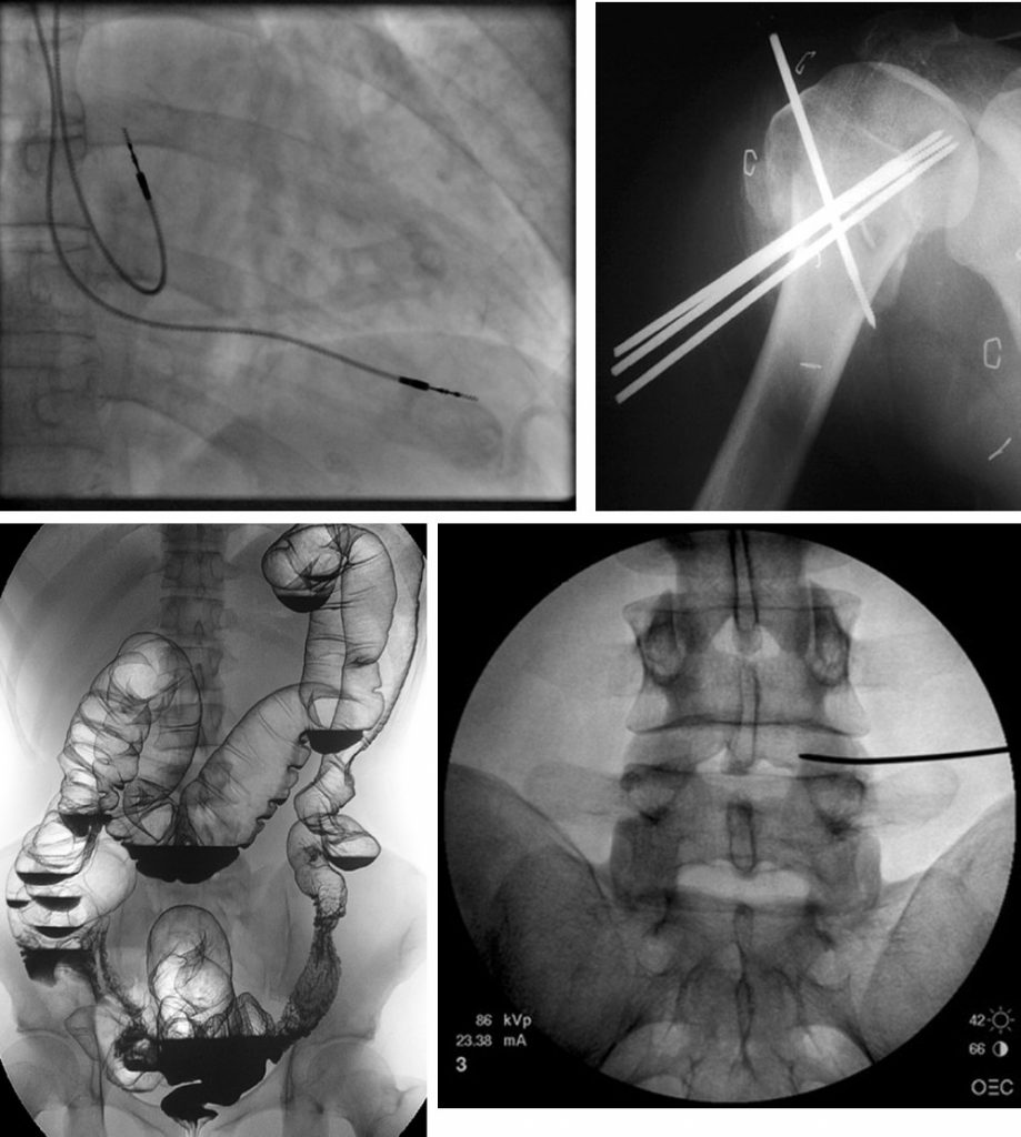
Fluoroscopy uses continuously emitted x-rays and allows real time visualization of anatomic structures. An x-ray tube located beneath the table emits a continuous x-ray beam that passes through the patient and falls onto a continuously fluorescing screen and image intensifier located above the patient. The fluorescing screen emits a faint light. The emitted light is amplified electronically by an image intensifier and the image displayed on a television screen. When an image of interest is identified, a radiograph may be obtained with a pulse of radiation. Image intensifier used in fluoroscopy substantially decrease the amount of radiation needed to produce clinically useful image.
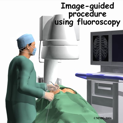
In modern medicine there are many fluoroscopic procedures, either diagnostic or therapeutic. The common procedures include investigations of gastrointestinal tract (barium swallow, barium meal), orthopaedic procedures (II guided fracture reduction, placement of metalwork), angiography (cerebral angiogram, angiography of peripheral limbs, cardiac angiography), placement of PICC, urological procedures (retrograde pyelography), implantation of cardiac devices (pacemakers, defibrillators) and pain management (discography).
Radionuclide imaging
The radioactive isotopes used in diagnostic imaging emit gamma rays as they decay. The gamma rays are electromagnetic radiation similar to x-rays. Gamma rays have higher frequencies and shorter wavelengths than x-rays. The radioisotopes used in medical diagnosis are artificially produced and most have short half lives. Radionuclide imaging depends on the fact that certain substances concentrate selectively in different parts of the body.
The gamma rays emitted by the isotope are detected by a gamma camera enabling an image to be produced. A gamma camera consists of a circular sodium iodide crystal coupled to a number of photomultiplier tubes. Light is produced when the gamma rays strike and activate the sodium iodide crystal and the light is then electronically amplified and converted to an electrical pulse. The electrical pulse is further amplified and analysed by a processing unit so that a recording can be made. Computer is linked to the gamma cameral to enable rapid serial images to be taken and to perform computer enhancement of the images when necessary.
References:
- Diagnostic Imaging, Peter Armstrong and Martin L Wastie. Blackwell Science
- Radiopaedia at https://radiopedia.org
- Ionizing radiation, WHO at https://www.who.int/ionizing_radiation/about/what_is_ir/en/
Recent Comments